Why a 3D Scan Is Not the Same as a CAD Model
If you arrived on this page, there is a good chance you need to convert a 3D scan into a usable CAD model. Perhaps you recently purchased a 3D scanner expecting to quickly obtain a clean and editable 3D model ready for production. This is one of the most common assumptions in the world of 3D scanning and reverse engineering. Unfortunately, the reality is often more complex.
Modern 3D scanners are extremely powerful tools. They can capture millions of points and reproduce the geometry of an object with impressive detail. Once processed into a watertight mesh, the scan data can often be used successfully for rapid prototyping and 3D printing. However, things become significantly more complicated when the final goal is manufacturing with CNC machining, engineering modification, or high-quality product redevelopment. A scanned mesh is not a CAD model.
The Difference Between Mesh Data and CAD Geometry
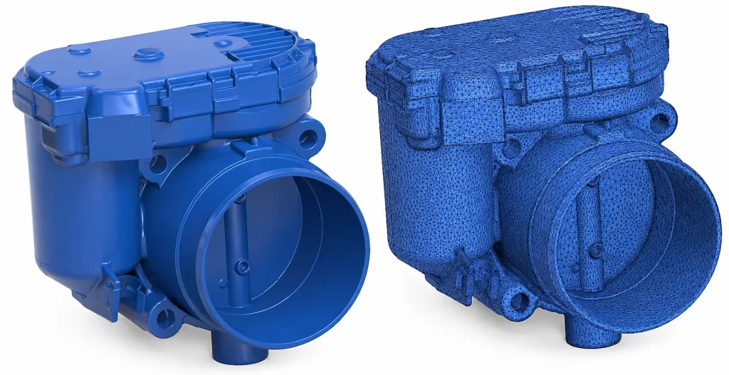
Most 3D scanners generate mesh data, typically in STL or OBJ format. A mesh is essentially a dense collection of triangles describing the external shape of an object.
While visually accurate, mesh data has several limitations:
- It is difficult to edit precisely
- It lacks parametric features
- It contains no manufacturing logic
- Surface continuity is often poor
- It is usually unsuitable for precision CNC workflows
- Large meshes can become extremely heavy and unstable inside CAD software
This becomes especially critical when surface quality matters.
For example:
- Automotive components
- Consumer products
- Aerospace parts
- Mold tooling
- Injection molded components
- Industrial design surfaces
- Mechanical interfaces and assemblies
In these cases, simply machining directly from a mesh often produces poor results, visible faceting, unstable toolpaths, or unacceptable surface finish quality.
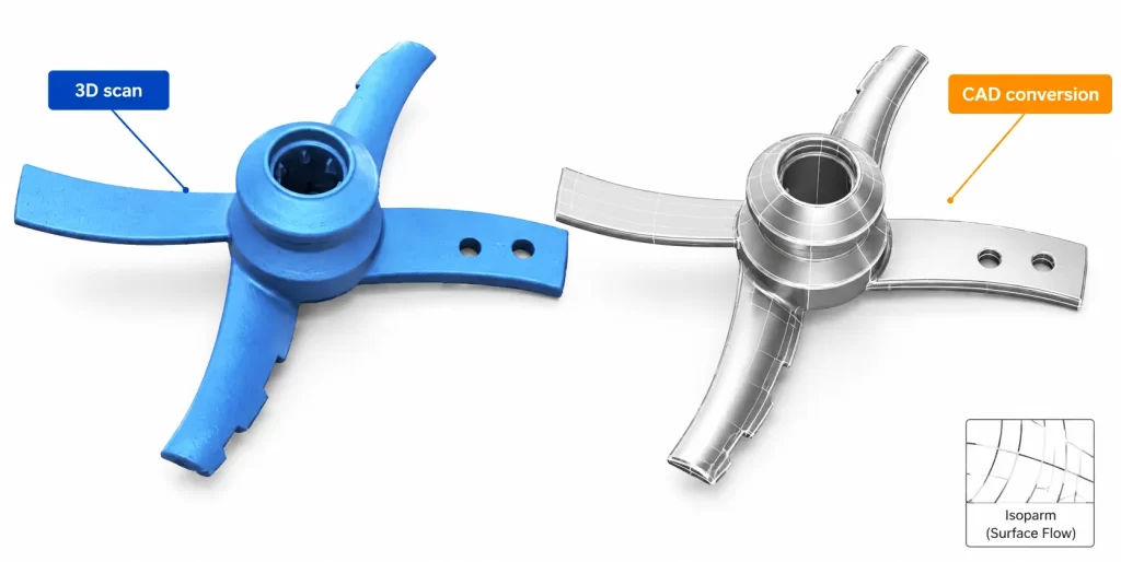
Reverse Engineering Is an Interpretation Process
One of the biggest misconceptions is believing that reverse engineering is an automatic conversion process. In reality, professional reverse engineering is an engineering interpretation process. The purpose is not simply to “trace” the scan, but to rebuild intelligent CAD geometry that behaves correctly inside a professional CAD environment and can be reliably manufactured.
This involves:
- Analyzing the original design intent
- Identifying functional geometry
- Reconstructing analytical surfaces
- Managing tolerances and symmetry
- Rebuilding fillets and transitions
- Improving damaged or worn areas
- Creating manufacturable geometry
- Producing stable and editable CAD models
A clean CAD model should not merely look correct. It must also behave correctly.
Why CNC Manufacturing Requires Better Geometry
3D printing is relatively forgiving. CNC machining is not. A CNC machine reacts directly to the mathematical quality of the surfaces it receives. Poorly reconstructed geometry often leads to:
- Visible machining marks
- Surface waviness
- Toolpath instability
- Inconsistent reflections on polished parts
- Difficult CAM programming
- Increased machining time
- Manual finishing and polishing work
This is why professional CAD reconstruction becomes essential when producing high-quality machined parts. The quality of the CAD model directly affects the quality of the final manufactured component.
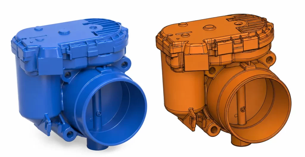
From 3D Scan to Editable CAD
At ThinkScan Solutions, reverse engineering is approached as a technical reconstruction process rather than a simple mesh conversion service. Using your scan data, we rebuild professional CAD models suitable for:
- CNC machining
- Product redesign
- Manufacturing
- Engineering modification
- Legacy part reconstruction
- Automotive restoration
- Prototype refinement
- Industrial production
Depending on the project, the final deliverables may include:
- Parametric CAD models
- NURBS surfaces
- Solid models
- Step, Parasolid or Iges files
The resulting CAD geometry is lightweight, editable, stable, and ready to integrate into your engineering workflow.
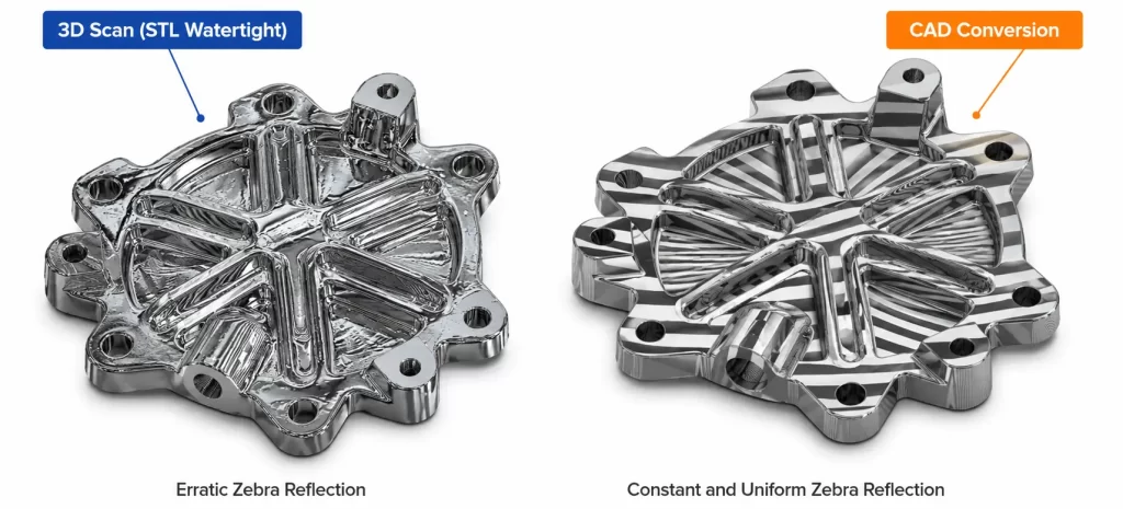
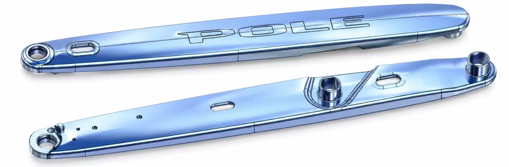
Surface Quality Comparison | Erratic Mesh Reflections vs Smooth CAD Surface Continuity
When Professional Reverse Engineering Makes Sense
Professional scan-to-CAD reconstruction becomes especially valuable when:
- Surface quality is critical
- The original CAD no longer exists
- The scanned part contains wear or deformation
- The object must be modified or redesigned
- The part must be manufactured accurately
- The geometry is mechanically functional
- The model must integrate into assemblies
- CNC machining is required
In many situations, investing in proper reverse engineering saves substantial time and cost later during manufacturing.
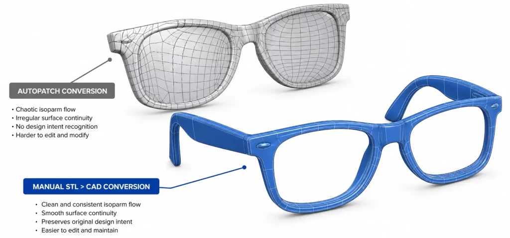
Not All Scan-to-CAD Workflows Are Equal
There is a major difference between:
- Automatically fitting surfaces onto a mesh
- And rebuilding intelligent engineering geometry
Automatic surfacing tools can sometimes produce visually acceptable results, but the resulting models are often difficult to edit, unstable, or unsuitable for precision manufacturing.
A professional reverse engineering workflow focuses on:
- Geometric logic
- Surface behavior
- Manufacturability
- CAD stability
- Long-term editability
This is particularly important for complex mechanical and Class-A style surfaces.
Need Help Converting a 3D Scan into CAD?
If you have scan data that needs to become a clean and editable CAD model, ThinkScan Solutions can help transform your mesh into production-ready engineering geometry suitable for manufacturing and further development. Whether the project involves mechanical components, automotive parts, legacy products, or freeform surfaces, the objective is always the same: Create CAD geometry that is not only accurate, but genuinely usable in the real world.
🌐 Get in touch
Explore services, case studies, and training opportunities: