Industry
- Automotive
What We Did
- 3D Scanning
- Reverse Engineering
- Exporting data: STL to STEP
Project Details
-
Carburettor Solex 4A1 (1970)
Engineering a Legacy Component -
3D Scanning Accuracy: ± 0.035 mm
Final CAD Accuracy: ± 0.05 mm (Average). Local deviations may vary depending on geometry and feature accessibility
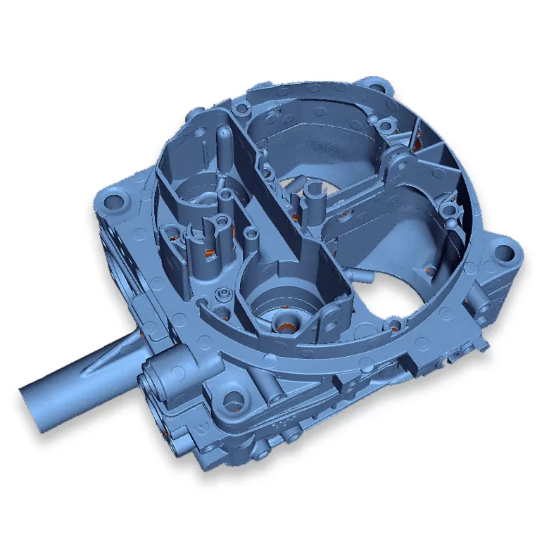
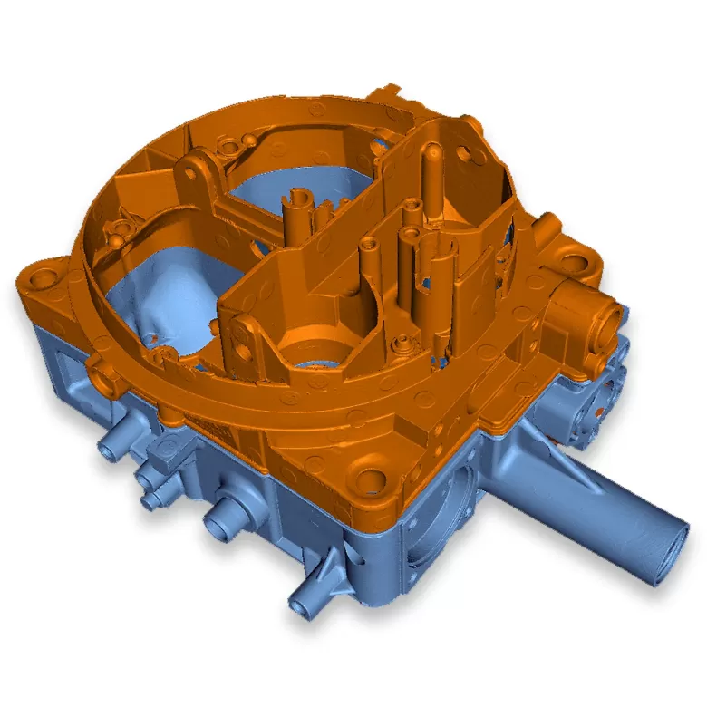
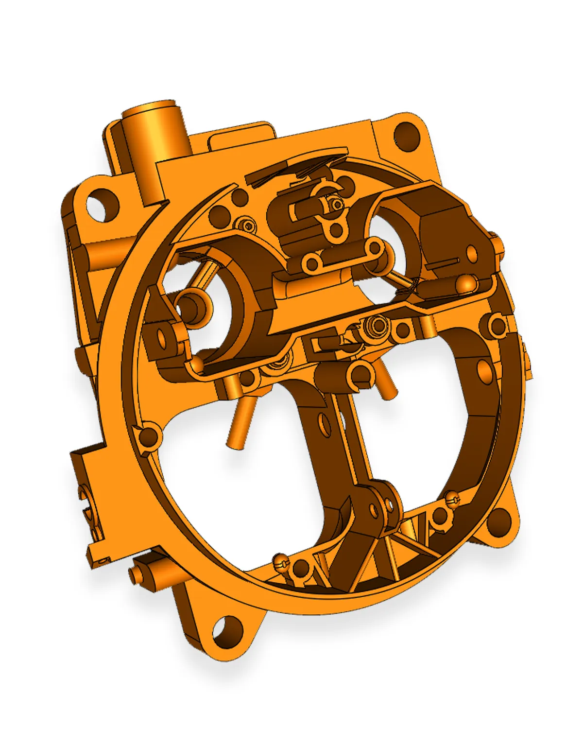
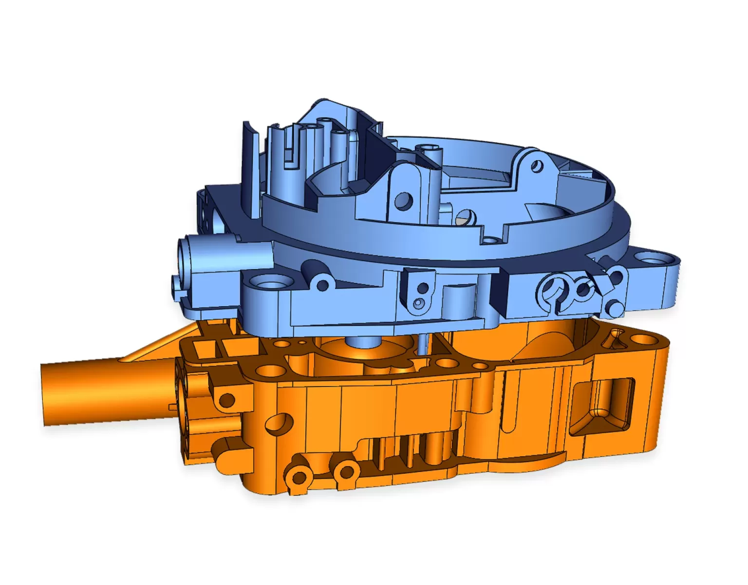
In this project, a vintage carburettor (Solex 4A1, 1970) was reconstructed into a fully parametric CAD model starting from the 3D scan of a real component that exhibited wear and slight deformation. As is often the case with cast parts of this type, the geometry of the physical component does not perfectly match what would be expected from an “ideal” design model.
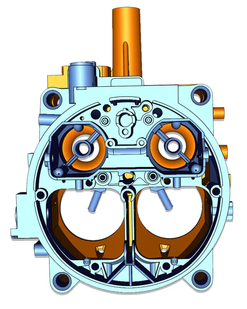
One of the main challenges concerned the mating surface between the two halves of the carburettor. The scan revealed a noticeable curvature of the base, a condition commonly found in components that have undergone decades of thermal cycling, clamping forces and residual stresses from the casting process. In the CAD model, this surface was therefore normalised and restored to a planar condition in order to ensure proper sealing and correct assembly between the two parts.
At the same time, other features such as holes and mounting points were deliberately not normalised or forced into symmetry. Although the component appears to follow a symmetrical design logic, the actual casting shows deviations of several millimetres. To avoid misalignment issues with interfacing components, these features were extracted directly from the scan and preserved in their real positions.
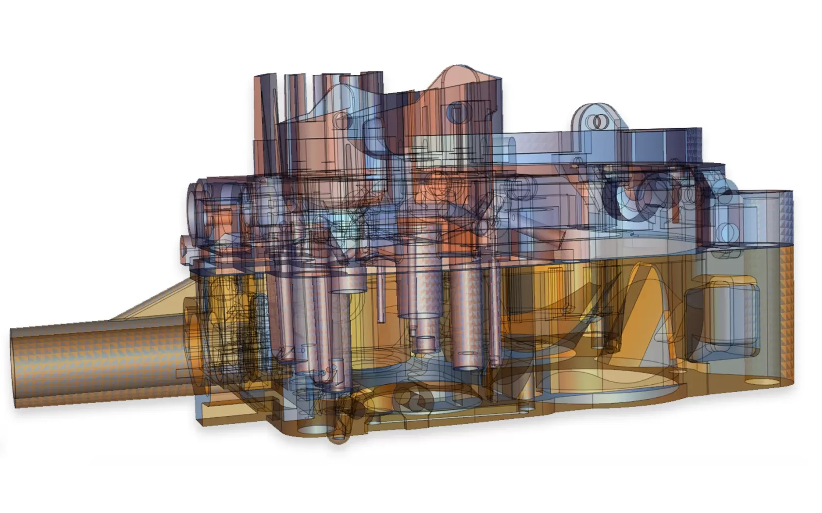
An additional layer of complexity was introduced by the internal channels of the carburettor, many of which have very small diameters (approximately 1–2 mm). In legacy components of this kind, internal passages are rarely continuous ducts; rather, they result from the intersection of multiple drilled holes executed from different directions during manufacturing. For this reason, the internal network was reconstructed in CAD using intersecting simple cylinders, a solution that reflects both the original manufacturing logic and the functional behaviour of the internal circuits.
Projects of this nature clearly demonstrate that reverse engineering is not a mere replication of scan data, but a process of technical interpretation. It requires the ability to distinguish between deformation of the physical part, original design intent, and assembly requirements.